TRANSLATE:
![]()
![]()
Visualize, Monitor, and Control Facility Equipment
 |
Background
Facilities equipment such as pumps, chillers, heaters, and abatement systems, can have a direct impact on manufacturing processes. Monitoring for excursions in facilities equipment has always been a major capability of FabGuard® FDC software. In FabGuard version 20.12.00 we significantly enhanced this capability by:
- Enabling direct visualization of the state of facility equipment.
- Providing real time data view from facility equipment.
- Providing direct control of facility equipment components such as motors and valves.
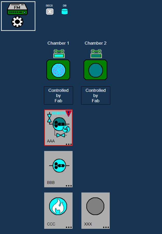
Figure 1: Facility Monitor (FM) Node Tool Layout of FabGuard Web showing a main pump, a booster pump, and an abatement system.
Benefit
A significant benefit to FabGuard facility monitoring is the factory's ability to mix and match facility equipment for each tool. Since FabGuard has a single unified user display regardless of equipment manufacturer, it is no longer necessary to use different proprietary monitoring software from each manufacturer. A factory can concentrate on purchasing best equipment for each manufacturing tool, knowing that FabGuard will visualize, analyze, and control the equipment in the sub-fab.
State Visualization
FabGuard Web provides visualization of fab, group, and tool layouts. The user can quickly see the state from the tool and process point of view, and with the new facility related enhancements, the user can now see the state of the facility equipment.
FabGuard can connect to three types of equipment:
- Main Pumps
- Booster Pumps
- Abatement Systems
Each piece of facility equipment is independently visualized in FabGuard (Figure 1).
Each piece of facility equipment consists of components. Which components are allowed depends on the equipment type. Table 1 shows a matrix of supported components by equipment type.
| Equipment/Component | Main Pump | Booster Pump | Abatement |
|---|---|---|---|
| Control | X | X | X |
| Motor | X | X | |
| Integrated Booster | X | ||
| Gate Valve | X | X | |
| Purge Valve | X | X | |
| Burner | X |
Table 1: Facilities equipment types and their supported components.
Each component can be in a specific state. Which states are allowed depends on component type. Table 2 shows the allowed states for each component.
| Component | Allowed States |
|---|---|
| Control | Local, Remote |
| Motor | Off, On Low, On |
| Built In Booster | On, Off |
| Gate Valve | Off, On |
| Purge Valve | Off, On |
| Burner | Off, On Low, On Medium, On High |
Table 2: Allowed states for each facilities equipment component.
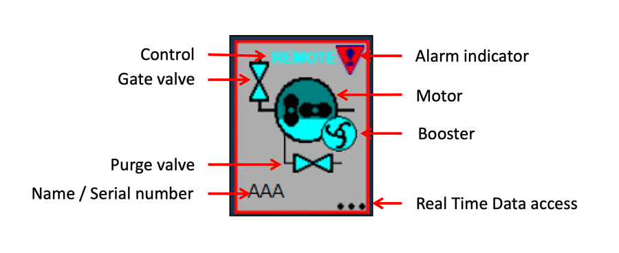
Figure 2: Visualization of a main pump with labeled components.
Configuration of facility equipment, components, and their states is performed in the FabGuard acquisition recipe. In addition to component state, FabGuard tracks the presence of Alarms on the equipment. If alarms are present, an indicator will be added to the facility icon (Figure 2). These alarm states will automatically clear if the alarm is resolved on the equipment. Additionally, FabGuard can add facility Alarms to the database for viewing historical data, user notification, and equipment interdiction.
Real Time Data View
FabGuard facility capabilities are intended not only for process/equipment engineers interested in the state of supporting facility equipment, but also for facility engineers who are focused on maintaining and enhancing facility equipment. When investigating facility equipment issues, it is important to access current data immediately. FabGuard Web provides direct monitoring of real time data from any facility equipment right from the facility equipment icon.
Figure 3 shows an example of facility data for a main pump. The display shows the state of all defined components, the state of all equipment alarms, and the real time values of pump parameters. This information is updated every five seconds.
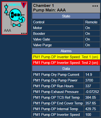
Figure 3: Real time state, alarm, and data for a main pump.
Control Facilities Equipment
In addition to visualizing the current state of facilities equipment, FabGuard can act as a Human Machine Interface (HMI) to provide equipment control. Authorized users can turn on/off each Equipment component. For example, a user can turn on/off pump motors and open/close pump valves.
Configuration of facility equipment control is performed in the FabGuard I/O subsystem by defining the commands used for state transitions of each component. For example, if the pump supports commands to turn the motor on and off, the user can define two I/O facility output channels configuring what message must be sent to the pump for each command. FabGuard will then automatically generate the necessary list of commands and make the list available in FabGuard Web.
Facility equipment commands must be issued from a specific web browser for safety. To issue a command two things must happen:
- A dedicated display physically next to the process tool transfers control to a dedicated display in the sub-fab.
- A facilities user must issue the control command from the dedicated display physically next to facility equipment.
The first requirement guarantees that the process/equipment engines have authorized the facility system for manual control. The second requirement guarantees that users working on the facility equipment are physically collocated with the equipment they are controlling.
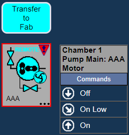
Figure 4: Sub-fab view of available commands configured for a pump main motor.
Figure 4 shows an example of commands configured for a pump main motor. The icon above the pump indicates that the pump is under control of the sub-fab.
Continued Development
FabGuard version 20.12.00 adds visualization and control of facility equipment specifically designed for facility engineers and technicians. Future enhancements to FabGuard will add:
- Chillers and heaters to the list of equipment types
- FabGuard Web views specifically for facilities monitoring at a large scale
- Facilities centric analyses
This future work allows facility engineers and technicians to focus on the needs of the sub-fab independently of the needs of the general factory floor.