TRANSLATE:
![]()
![]()
![]()
Water Tight Does Not Always Mean Water Tight – How to Derive a Correct Leak Rate Test Specification
Billions of components, subassemblies and assembled vehicles are tested for leakage every year in the automotive industry. For each leak test, a leak rate test specification must be set, i.e. what leak rate will still be considered "okay" and what leak rate is defined as too large or "not okay."
Why leak testing?
To understand how to determine the correct leak rate setting, it is required to first understand why a component or subassembly needs to be tested for leaks. A good question to ask is: "what needs to be prevented?" Sometimes a leak can cause damage to a part or system or to the user of the product. There may also be environmental concerns about leakage which are laid out in a regulation that needs to be fulfilled.
If the failure that needs to be prevented is described (and sometimes there can be more than one failure which needs to be prevented), the next step is to categorize the leakage.
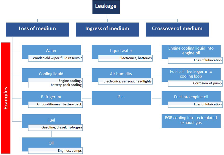
Types of leakage
All leakage cases can be categorized into these general three categories:
- the medium should be contained in a part or system (as a loss of that medium might cause damage)
- the ingress of a different medium into a part or system
- the crossover of one medium into the loop operated by a second medium
How to derive the correct leak rate specification
For some cases, clear regulations exist for the maximum leak rate to be guaranteed. The most prominent case is regulation for the maximum allowable leak rates of refrigerant in an air conditioner.
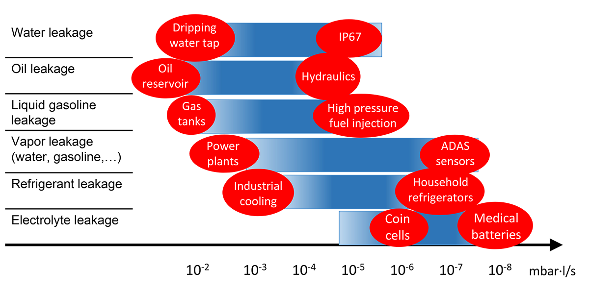
Sometimes simplifying tables are consulted that show which leak rates to apply for which medium. These tables can be misleading as there is not just one specification for each medium. Watertight does not always mean watertight for example, when you are looking at water loss in a power plant or at water ingress into an electronics part.
A maximum allowable amount of leakage needs to be set for each component in its application scenario and a leak rate specification can be derived from there. For liquid leakage, for example, this can range from a small amount of liquid being tolerable to no leakage at all. For gas leakage, no leakage is technically impossible.
Example: Loss of water-glycol cooling liquid
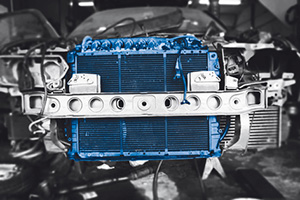 Water-glycol has been used in engine cooling for many centuries. If the engine loses cooling medium, the risk is that the engine starts overheating and will finally break down. However, a small amount of coolant loss will simply be backfilled from a cooling reservoir. Small amounts will also evaporate quickly in the warm and well vented engine compartment. Typically leak rate specs in the 10-3 mbar·l/s are used for this application.
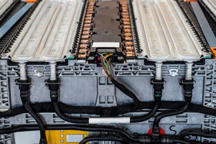 Modern drive train batteries also often use cooling loops with water-glycol mixtures. The requirements for containing this liquid, however, are much more challenging. Even small amounts of water-glycol loss can get in contact with electronics and may cause electric shortage. So the allowable amount of water-glycol leakage needs to be set to much lower levels compared to the engine cooling application. These cooling loops need to be tested for leak rates in the 10-4 to 10-5 mbar·l/s range (also depending on the operating pressure).
Other factors influencing the leak rate specification include:
- temperature
- operating pressure
- material combination
- regulations
Operating pressure, in particular, has a huge impact on the amount of leakage. The higher the operating pressure of a fluid, the higher the leak rate caused by any defect will be. And the rise is not linear but the leak rate increases with the pressure to the second power (q~ p²).
Example: Fuel leakage
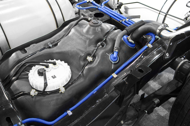 In internal combustion engine (ICE) vehicles, fuel leakage must be prevented in several parts, including the gas tank, fuel supply lines, and the injection systems. In the gas tank and in some fuel supply lines and pumps, the fuel is contained in liquid form and in the fuel injection system and in the high pressure fuel pump, the gas is contained in gaseous form. Also the pressures vary significantly from atmospheric pressure in the gas tank to up to 2,000 bar in the fuel injection system.
 To prevent liquid leakage of gas tanks, a leak rate spec of 10-3 mbar·l/s might be sufficient, however, strong regulations for carbon hydrogen emissions from gas tanks as vapors often require more stringent testing. The low pressure side of the fuel system is typically tested for a leak rate in the 10-4 mbar·l/s range, whereas the high pressure side of a fuel injection system requires leak testing down to the 10-5 ..10-6 mbar·l/s.
Also for water ingress, very different specifications may be required depending on whether the ingress of just liquid water is to be prevented or whether also intake of humidity can cause a problem. For liquid water ingress at close to atmospheric pressure typically leak rates in the 10-3..10-5 mbar·l/s need to be achieved whereas leak rates in the 10-6 mbar·l/s and lower are required to prevent ingress of humidity.
Individual specifications for each application scenario
Many factors influence the correct leak rate specification a component or system should be tested for.
INFICON offers some guidelines for reoccurring cases. However, the exact conditions may be different for each real life case so each case must be decided individually based on the exact application scenario.
If you need to decide on a leak testing specification for a specific component or subsystem, we can help - contact us for support.