Creating a Signal Bin Filter to Remove Erroneous Data
Problem Statement
Tool: 200mm Chemical Mechanical Polish (CMP)
General: The polish head spin speed Status Variable ID (SVID) in revolutions per minute (RPM) is intermittently reported as “zero” during the main processing step of a tool recipe. The complication is that the tool is actually reporting a number, zero, and not reporting an empty value when data is dropped. Because the tool is reporting zeroes, subsequent statistical calculations are incorrect and produce false processing failures. We need to develop a filter that will eliminate the incorrect data points and produce valid statistical calculations. This filter is easy to create and propagate using the Signal Bin interface of FabGuard.
Solution
Head RPM Filtering
When the Head RPM variable is noticed to be reporting zeroes instead of real data, the first activity performed was to verify in the communication log that the tool was returning zero values from Status Variable Identification (SVID) 208. As expected, the tool was responding with zeros during this time of the process (Figure 1.)

Figure 1: A portion of the communication log showing zeros for Head RPM.
Additionally, two other parameters were also reporting zeros and were part of the same SVID, just different elements in the string, Platen RPM [index1] and Inner Tube State Set Point [index2] (Figure 2.)
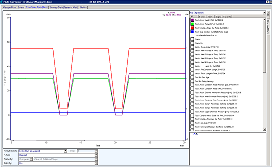
Figure 2: A portion of the communication log showing zeros for Head RPM.
The filter was created using a Signal Bin in FabGuard. There are four conditions that need to be met in order to determine if the data can be ignored. If all four conditions are met, then a “0” is placed on the Signal Bin stack, if not, then a “1” is placed on the stack (Figure 3.) Setting rigid conditions reduces the chance that valid readings of zero will be eliminated. The four conditions are:
- Head RPM must equal exactly ZERO.
- Platen RPM must equal exactly ZERO.
- InnerTube State Set Point must equal exactly ZERO.
- Step Number must NOT equal ZERO (This makes sure the tool is processing).
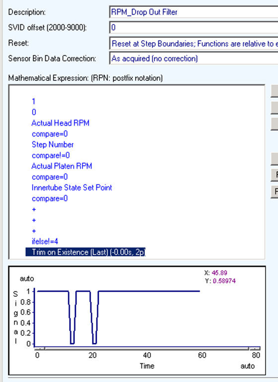
Figure 3: The Signal Bin logic that determines whether a data point can be ignored.
A Drop Out Filter Counter was also created to see how often this issue was occurring during a run. The count increases every time the RPM Drop Out Filter passes through a level of 0.5 (Figure 4.)
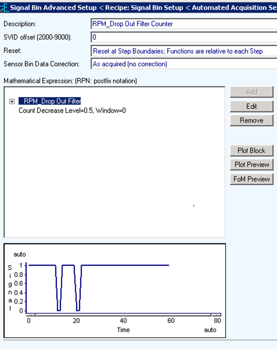
Figure 4: The Signal Bin logic for the drop out counter. The first plot shows the drop outs occurring in time. The second plot shows the counter at one and then two events during the run.
Figure 5 shows a report of the RPM Drop Out Filter counter. The interesting fact is that only tools 403, 404, and 405 have this issue and it happens quite frequently. Although this article does not address the issue of root cause, this problem could result from a specific tool software revision or hardware configuration. The report also highlighted an additional problem where the Drop Out filter was being triggered at the end of a process run. This is the reason for the trim of the last two points at the end of the Drop Out Filter’s Signal Bin (Figure 6.)
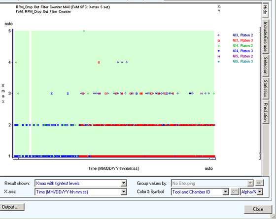
Figure 5: The RPM Drop Out Filter counter report.
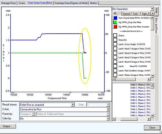
Figure 6: The RPM Drop Out Filter time series data showing the need to trim the last two data points.
Once the RPM Drop Filter logic was validated, it was implemented through simple logic to pass only the RPM data if the filter was equal to 1. Four Signal Bins were created, one for each Head RPM data Bin (Figure 7.)
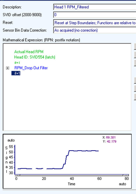
Figure 7: The RPM Drop Out Filter applied to the Head RPM data Bin and the resulting data plot.
Tool Platen Recipe Consolidation Using FabGuard’s Acquisition Dictionary
After the filter Signal Bin development was complete, the next issue was how to populate these Filtered Head RPM Signal Bins to all platens on all tools. The challenge was that each platen on each tool had its own recipe, 15 data collection recipes in total. Through the use of FabGuard’s Acquisition Dictionary, the runs were imported from each tool to create the Alias Bins for each Platen (Figure 8.) Not only did the Acquisition Dictionary consolidate from 15 recipes to 5 recipes, one platen recipe for each of the 5 tools, the variable names used in the recipes were standardized into a single naming convention (Figure 9.) After testing the current consolidation, these 5 tool recipes could be further consolidated to 1 recipe used by all platens.
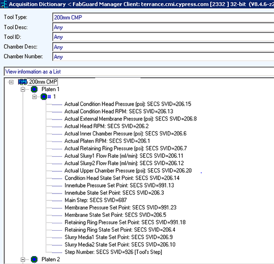
Figure 8: FabGuard Acquisition Dictionary showing the Tool Bins for platen 1.
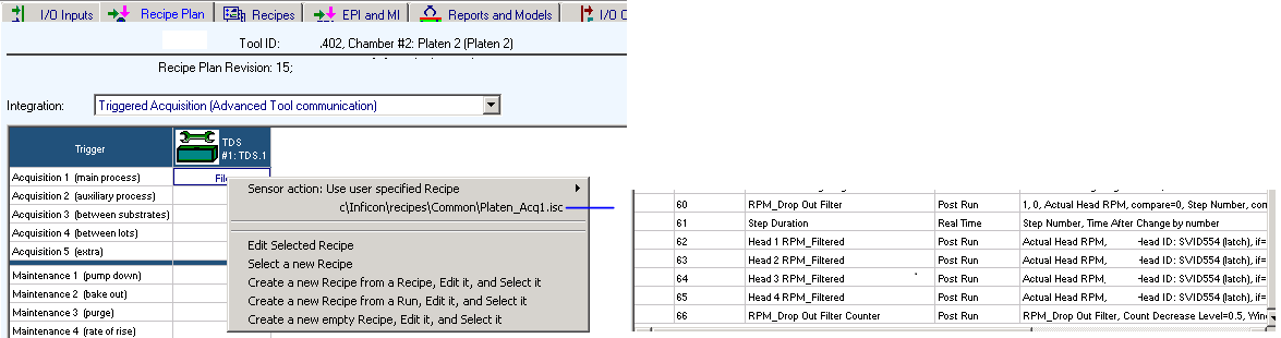
Figure 9: Assigning the new FabGuard recipe that includes the filtered Signal Bins to the Acquisition 1 process.
Report Results
The Signal Bin filter had a significant impact on the statistics calculations for the Head RPM data (Figure 10.) The Report limits do not need to be artificially wide in order to prevent false failures from erroneous data.
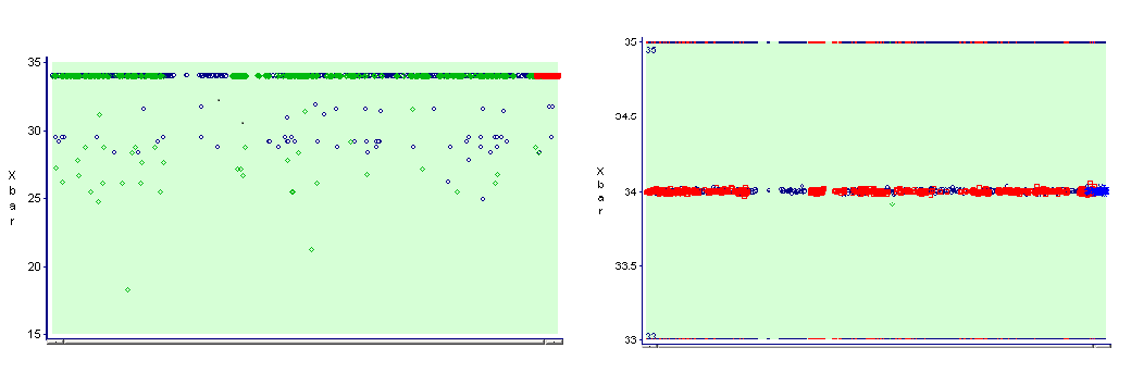
Figure 10: The first report of head speed is without the Signal Bin filter applied. The second report is of the head speed with the Signal Bin filter applied.
Conclusion
Using FabGuard’s Signal Bin and Acquisition Dictionary interfaces allowed us to quickly and easily develop and deploy a filter that would eliminate bad data when the tool reported the data value incorrectly. The calculated statistics became more reliable and the factory FDC was improved.