May 2018
FabGuard APC v5.00.03 Release »
Metric History in FabGuard Web »
New RGA Features beyond FabGuard version 854 »
FabGuard eOCAP Workflow Framework »
No Logistics from Tool or MES? Try Assigning Them from Signal Bin Logic! »
Understanding Host Name Resolution »
Change the Properties to Make Sure FabGuard Executive Runs as an Administrator »
FabGuard Auto Start and Windows Update Support for Windows 10 »
End-of-Life Support for FabGuard Versions and Microsoft Products »
Using an SSR to Invert the Controlling Signal of a National Instruments TTL Digital Output in FabGuard
Overview
The purpose of this application is to use a solid state relay (SSR) to invert a signal provided in continuous operations using FabGuard. Inverting a signal is necessary when the desired output signal does not match the provided digital output signal. By adding in a high quality Single Pole Double Throw (SPDT) relay, the desired output signal can be achieved in order to stop processing on the equipment and prevent costly scrap events.
Background
Automatically shutting down the RF generator when fault occurs limits scrap events to a single wafer per chamber fault. Without the automatic shutdown, hundreds of wafers could be scrapped per chamber fault. In practice, an output fault was needed to interrupt a door interlock switch which would cause the RF generator to shut off when a fault occurs. Manual intervention would be required to restart the generator.
The door interlock switch was set up with a constant applied voltage. Any break, such as opening the door, would open the circuit causing the voltage to drop to zero. This voltage drop then caused the tool to generate a fault and shut off the RF generator.
When initially configuring the output alarm in FabGuard using TTL Out output, the reset value was set to High with the logic to Negative (Low = On). The output would have the default good state passing a voltage and cause the fault to simulate the door opening (0 V upon fault). While the fault did do this, it was found that whenever the condition had to be set to a high value, it also performed a momentary reset to 0 V before providing a continuous voltage. This brief lapse in voltage caused the door interlock to think it had been tripped and faulted the RF generator.
Testing the inverse logic, reset value to Low with the logic to Positive (High = On), works as expected. The momentary reset of the voltage to 0 works in this case because 0 V is the default “good” condition and does not trip the interlock, nor does it go to a High value with voltage passed as part of the reset. This logic works, however, is not ideal and an SPDT relay was implemented to ultimately provide a cleaner solution.
Solution
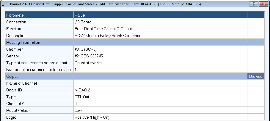
Figure 1: I/O Channels for SPDT Relay with Normally Closed Condition.

Figure 2: Industry standard SPDT SSR.
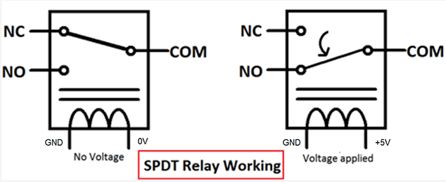
Figure 3: Internal working of SPDT Relay.
By utilizing an SPDT relay, the second scenario (Figure 1) which does not impact the reset can be used to get the same result as the desired first scenario would provide.
For our solution, an industry standard SPDT SSR was used to accomplish the signal inversion (Figure 2).
The SPDT utilizes wired connections for the door interlock, normally closed NC and common COM, and for the power source. An industry standard breakout box with 5V capabilities was used in this application with +5V connected to A1+ COIL and the digital ground DGND connected to A2- COIL. This allowed the circuit to function as desired depending on the situation (Figure 3).
For the “good” condition of 0 V, no voltage is being applied to the coil so the door interlock switch is being made, providing the continuous voltage in that circuit and not tripping the interlock. For a “fault” condition, a voltage is applied to the coil so the door interlock switch is broken, causing the door interlock to fault and shutting down the RF generator. This allows the FabGuard TTL Out logic to work as desired where a voltage break only occurs when a fault occurs.
Summary
After implementing this solution, the potential scrap from an RF generator fault has been reduced from hundreds of wafers down to just a single wafer.