Using FabGuard FDC for Back-End Processing
Following the success of FDC solutions in front-end wafer processing, several semiconductor manufacturers have chosen to implement FDC in their back-end wafer assembly processes (Figure 1). Applying FDC to the unit operations of back grind, dice, and wire bond is the highest priority for these manufacturers.
FDC implementation at the later stages of the semiconductor production process is even more important than at the earlier stages of the process. Each completed process adds value to a wafer; by the time a wafer reaches back-end processing its value is very high and faults are more costly. There is additional benefit to semiconductor manufacturers in the analog space. Analog assembly costs up to 35% of the total production cost. Compare this to logic assembly, which is only 15% of the total production cost [1].
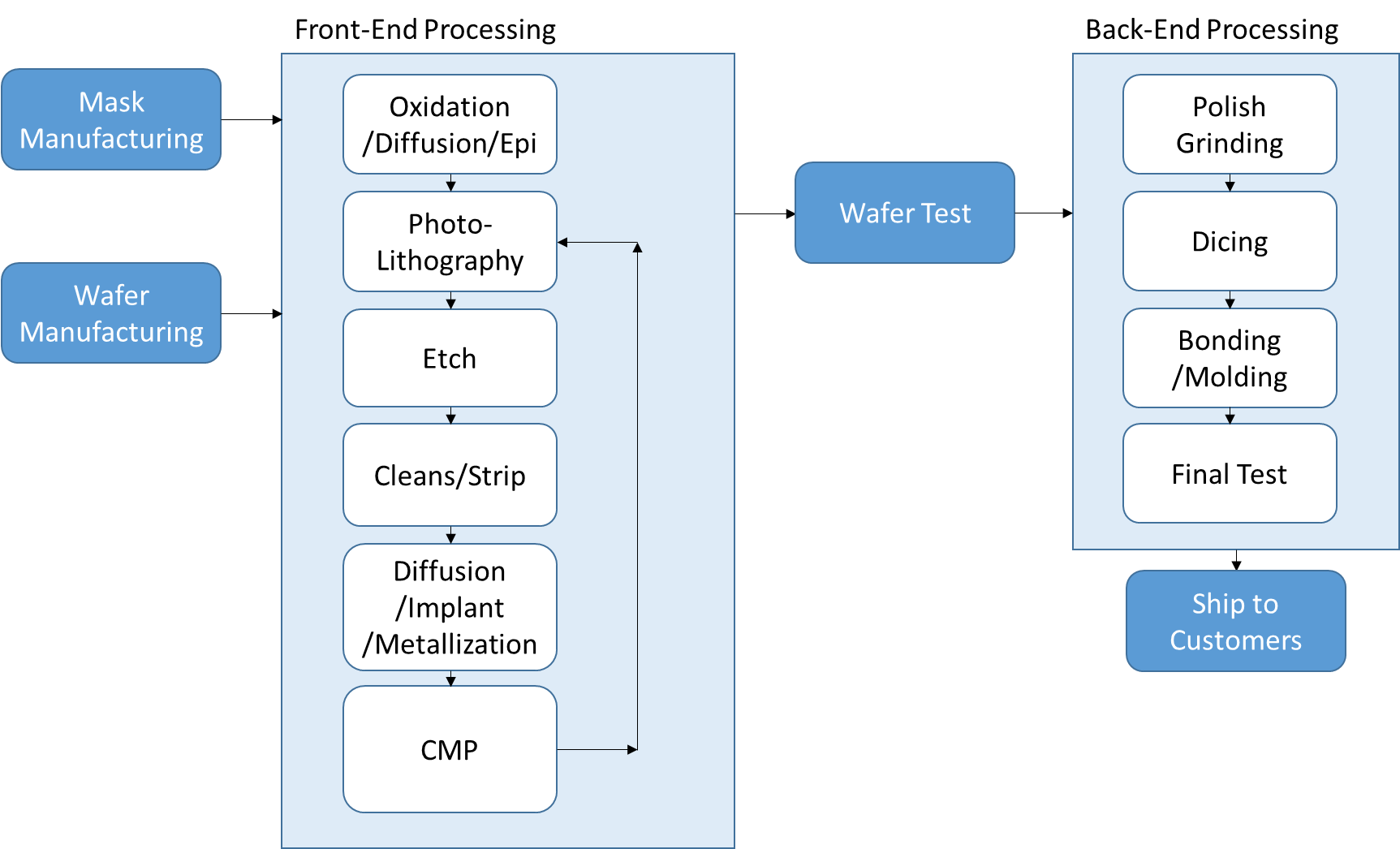
Figure 1: Semiconductor fabrication process flow.
Data Collection Methods
Two primary methods of data collection are used to accommodate the diversity of back-end processing equipment:
- SECS communication
- File import
Many modern back grinders, dicers, and wire bonders support SECS communication standards, which is the preferred method of data collection. File import is used when a tool does not support SECS communication, or the data recorded in the file has better fidelity than the data obtained via SECS communication.
Back Grind Example
The first step in back-end processing is to grind the back of the wafer to the desired thickness. FabGuard FDC was implemented on an industry standard Polish Grinder tool using SECS communication at 1 Hz. The challenge with this particular grinder was the number of different process units within the tool. Active data collection was configured for two grinding stations, a polish station, a spinner station, a UV station, an OCR station, and for tool level facilities management.
The FDC implementation focused on monitoring the following grinding station parameters: spindle torque, wheel speed, chuck speed, and coolant water supply. Like front-end process monitoring, back-end process monitoring depends on tool utilization and product mix. The methods for detecting process failure need to account for these changes in operating conditions.
Dicing Example
After the wafers have been ground to the desired thickness, the individual chips are cut along the kerf lines to prepare them for wire bonding and packaging. FabGuard FDC was implemented on industry standard blade and laser dicing tools using SECS communication at 1Hz. For dicers that use blades for cutting, the following parameters were monitored: rpm, blade current, and cooling water flows.
The actual cutting of the kerf can be less than 10 seconds in duration. The typical SECS communication rate of 1Hz may not be sufficient to detect all cutting faults. An external sensor that collects data at a faster rate can allow the data to be summarized by each kerf cut if needed.
Wire Bond Example
Successful deployments of FabGuard FDC on industry standard wire bonders have employed the use of file importers. The bonding process at each bond site is relatively fast, ranging from less than one second to approximately two seconds. Using SECS communication to collect this data at less than 1 Hz is difficult for most tools.
A majority of tool vendors provide a data file at the end of each wafer process that contains the time series data for each bond site. Since this file format is standardized across bonder manufacturers, the configuration of FDC using this method of data collection is quick and straightforward. The parameters typically monitored are component temperatures and overlay (offset from target). Figure 2 shows an example of a clear improvement of overlay performance after maintenance on a tool was performed.
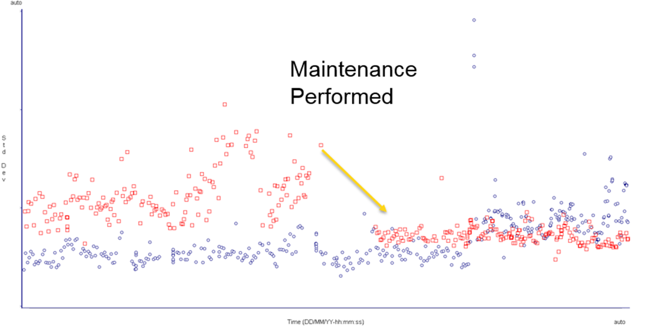
Figure 2: Standard deviation of overlay vs. time for two wire bonding tools, before and after maintenance.
Summary
FabGuard FDC has been successfully implemented on back grind, dice, and wire bond back-end processing tools. Back-end FDC provides additional protection to the manufacturing process when wafers are at their highest value.